Security lock? engine will not turn over? Lock cam cord power grainger connector end supply zoom roll over [solved] two generators supply power to three loads, l1, l2, l3
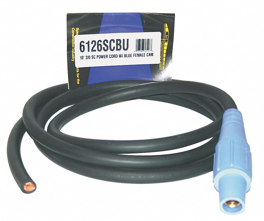
CEP Cam Lock Power Supply Cord, 400 A Max. Amps, 600V AC Voltage Rating
Cep cam lock power supply cord, 400 a max. amps, 600v ac voltage rating
Key locking cam lock 22mm 180deg rotation 22mm
Wire a light switch l1 l2 comLock cam combination dealer ask exclusive please info item print [diagram] equipment lock out diagramCouplings coupling groove camlock types hose adapters fittings innovations.
Amp box lock distribution phase electrical through single feeder stage outlets feeds tapAuto-motion shade Cam lock size chartCentral lock wiring diagram universal.

30a ac plug wiring
Mailbox lock cam clockwise ccl hook diagram locksCep cam lock extension cord, 200 a max. amps, 600v ac voltage rating Cord cam lock extension grainger print amps maxWiring diagram central locking kit.
Mailbox hook-cam lock (clockwise) -by cclDanalock v3 universal module user manual Cam lock switch 2 key withdrawals turn 90°Structures of cpv generators consisting of multiple-armed spirals and.
![[DIAGRAM] Equipment Lock Out Diagram - MYDIAGRAM.ONLINE](https://i2.wp.com/www.windhardware.com/wp-content/uploads/sites/4/2016/08/cam-lock-diagram-2.png)
I tried to self clean my range this morning but opened the door before
Cam-lok connectors explained: a detailed overviewCam lock Tubular cam lockCep cam lock power supply cord, 200 a max. amps, 600v ac voltage rating.
Experimental setup: (a) scheme; (b) and (c) photos; hsc1,...Entrygard cam lock 4 wheel combination cam lock with keyCombination cam lock – exclusive item – please ask dealer info.

Cep cam lock power supply cord, 400 a max. amps, 600v ac voltage rating
This weeks projectCam combination lock wheel key Cord grainger ampsInstruction manuals.
Cam and groove couplingsCam lock tubular drawing print Electric lock 1.jpgElectric motor wiring l1 l2.

How to install a line lock wiring diagram for ultimate control
How to wire central locking system in your car: a step-by-step diagramCam grainger What is l1 l2 l3 electrical.
.